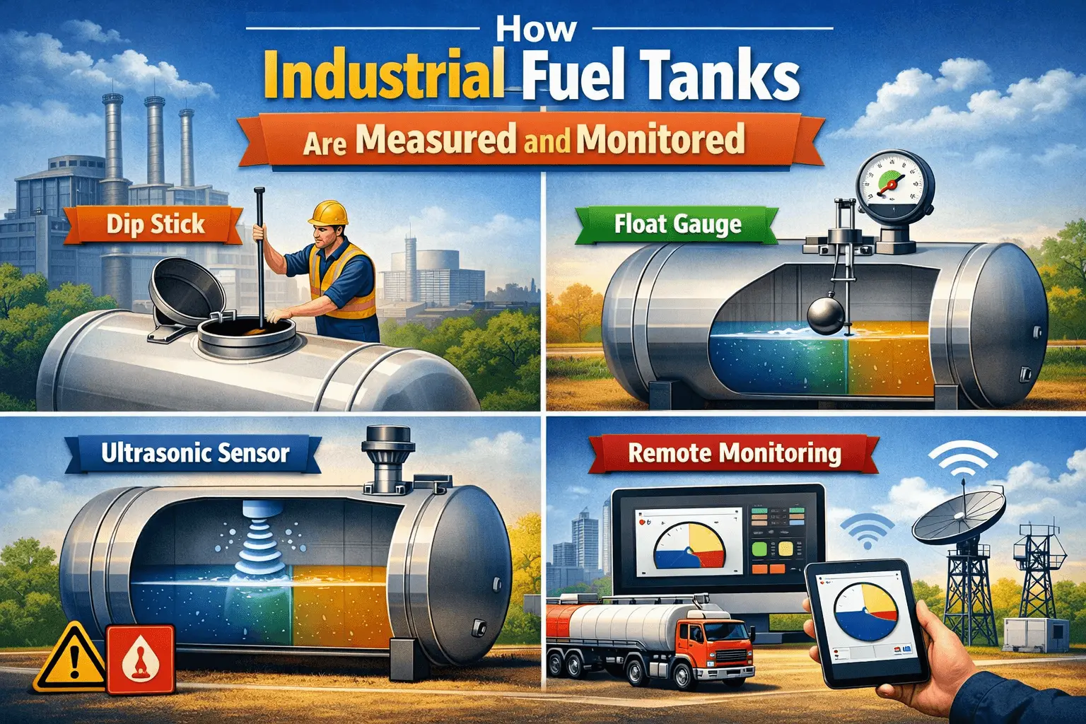
| ⚙️ Industrial fuel tanks store millions of litres of diesel, petrol, crude oil, and chemical fuels — often under pressure, in hazardous environments, and subject to strict regulatory standards. Accurate industrial fuel tank measurement and reliable fuel tank monitoring systems are essential for safety, cost control, and environmental compliance. |
An industrial fuel storage tank is not simply a large container. It is a precision-engineered system operating within strict limits for pressure, temperature, and fill levels. Using proper industrial fuel tank measurement methods ensures accurate readings and prevents costly errors. Even a 2% volume discrepancy in a 500,000-litre crude oil tank can result in 10,000 litres of unaccounted fuel — causing significant financial losses.
Beyond financial risks, poor fuel tank level measurement and monitoring can lead to overfills, leaks contaminating groundwater, and dangerous vapour buildup. Modern industrial tank monitoring systems help prevent these issues by providing real-time data and alerts.
Today, industrial fuel tank measurement has evolved from manual stick gauging to advanced systems using radar, ultrasonic sensors, pressure transmitters, and cloud-connected SCADA platforms. These technologies improve accuracy, efficiency, and operational safety.
This guide explains how industrial fuel tanks are measured and monitored, the technologies involved, and the safety systems that protect personnel, assets, and the environment.
Industrial Fuel Tanks Are Measured and Monitored
Overview of Industrial Fuel Tanks
Industrial fuel tanks vary enormously in size, shape, and application. Understanding the tank type determines which measurement and monitoring systems are appropriate.
| Tank Type | Typical Capacity | Common Contents | Key Standard |
| Atmospheric Storage Tank | 1,000 – 100,000 m³ | Crude oil, diesel, petrol, chemicals | API 650 |
| Floating Roof Tank | 10,000 – 200,000 m³ | Volatile crude oil, petrol | API 650 Annex C |
| Fixed Roof Tank | 500 – 50,000 m³ | Diesel, fuel oil, chemicals | API 650 |
| Pressurised Bullet Tank | 10 – 500 m³ | LPG, propane, butane | ASME Section VIII |
| Underground Storage Tank | 5 – 200 m³ | Petrol station fuel, diesel | EPA 40 CFR Part 280 |
| Horizontal Cylindrical Tank | 10 – 1,000 m³ | Diesel, chemicals, water | API 12F |
The 10% Ullage Rule
| ⚠️ | The Universal Safe-Fill Standard Industrial fuel tanks are never filled to 100% of their calculated geometric capacity. A minimum 10% ullage (empty headspace) is maintained as standard practice worldwide. This buffer accommodates thermal expansion of the stored fuel, prevents overflow during delivery, and provides space for vapour management systems to function safely. A 50,000-litre tank has a maximum working capacity of 45,000 litres. |
→ Diesel Tank Volume Calculator (with 90% fill level) →
→ Horizontal Tank Volume Calculator →
Tank Gauging Methods: From Manual to Automated
Tank gauging refers to the process of measuring the liquid level in a storage tank to determine the volume of contents. The method used depends on tank type, required accuracy, regulatory requirements, and budget.
Manual Gauging: The Traditional Baseline
Despite the availability of sophisticated electronic systems, manual gauging remains in widespread use — particularly for secondary verification, calibration checks, and in smaller facilities. Manual methods include:
- Dip tape (ullage tape): a calibrated steel tape with a plumb bob and water-finding paste lowered into the tank through a gauge hatch. The reading shows the distance from the reference datum to the liquid surface.
- Gauge glass (sight glass): a transparent tube connected to the tank body showing the liquid level directly. Effective for small to medium tanks operating at low pressure.
- Bob and tape: a weighted float on a calibrated tape that rises and falls with the liquid level, read through an indicator on the tank top.
| 📋 | Manual Gauging Limitations Manual gauging is labour-intensive, requires personnel to physically access the tank top (a safety risk for large atmospheric and pressurised tanks), introduces human reading error, and provides only a snapshot measurement rather than continuous monitoring. For custody transfer and inventory management in large industrial tanks, manual gauging alone does not meet modern accuracy requirements. |
Modern Tank Gauging Sensor Technologies
Electronic tank gauging (ETG) systems use sensors to measure level, temperature, pressure, and density continuously — feeding real-time data to control systems and remote monitoring platforms. The following are the primary technologies in use across modern industrial fuel facilities.
| 📡 Radar Level Measurement Non-contact, high-precision — the gold standard for large atmospheric tanks |
| How it works: A microwave radar signal is emitted from an antenna mounted at the tank top. The signal reflects off the liquid surface and returns to the sensor. The time of flight is precisely measured and converted to a liquid level reading. Two variants exist: Guided Wave Radar (GWR) uses a probe submerged in the liquid for high-accuracy readings in turbulent or vapour-rich environments; Free Space Radar (FSR) operates without contact and is preferred for large crude oil and fuel tanks. ✔ Advantages: Accuracy to ±1 mm. No moving parts. Unaffected by liquid density, vapour, or foam. Works in hazardous (ATEX) zones. Preferred by API MPMS (Manual of Petroleum Measurement Standards). ⚠ Limitations: Higher initial cost than mechanical gauges. Antenna fouling in heavy crude applications. Requires careful mounting to avoid false echoes from tank internals. |
| 🔊 Ultrasonic Level Sensors Sound-wave measurement — cost-effective for medium-accuracy applications |
| How it works: An ultrasonic transducer emits high-frequency sound pulses that travel through the air above the liquid surface, reflect back to the sensor, and are timed to calculate the distance to the liquid surface. The level is derived from the known distance from sensor to tank bottom. ✔ Advantages: Lower cost than radar. No contact with liquid. Easy installation on existing tanks. Suitable for most fuel types. ⚠ Limitations: Affected by temperature gradients in the vapour space (speed of sound varies with temperature). Not suitable for pressurised tanks. Accuracy of ±3–5 mm — lower than radar. Foam and vapour can cause false readings. |
| 📊 Pressure Transmitters and Hydrostatic Level Gauging Liquid pressure as a proxy for fill depth |
| How it works: A pressure transmitter is mounted at the tank base or on a dip tube. The hydrostatic pressure of the liquid column above the sensor is measured and converted to a liquid level. For density-compensated measurements, a second transmitter at a higher elevation allows the system to calculate actual liquid density and correct the level reading accordingly. ✔ Advantages: Reliable, simple, low maintenance. Works in pressurised tanks. Can provide density and mass measurement. Good for underground and enclosed tanks where top access is limited. ⚠ Limitations: Accuracy depends on liquid density stability. Not suitable for floating roof tanks (variable vapour space). Requires regular zero-point calibration. Fouling of the transmitter diaphragm in heavy or viscous products. |
| 🌡️ Multi-Point Temperature Sensors Temperature correction for accurate volume-to-mass conversion |
| How it works: Industrial fuels change density significantly with temperature. A 1°C rise in diesel temperature causes approximately 0.07% volume expansion. Multi-point temperature sensor strings — typically 8 to 16 sensors distributed at different depths through the tank — measure the average product temperature. This allows the system to convert observed volume at ambient temperature to volume at standard temperature (15°C in the petroleum industry). ✔ Advantages: Essential for custody transfer accuracy. Corrects for thermal stratification in large tanks. Required by API MPMS Chapter 7 for fiscal measurement. ⚠ Limitations: Adds installation and maintenance cost. Temperature string must span full liquid column. Stratification modelling requires sophisticated averaging algorithms. |
| 🔺 Float and Tape Systems Electromechanical gauging — durable and proven |
| How it works: A float rests on the liquid surface and is connected by a perforated steel tape running over a serrated drum to an encoder. As the liquid level changes, the float rises or falls, the tape moves, and the encoder sends a level signal to a local display or transmitter. Float and tape gauges have been in industrial use for over 80 years and remain highly reliable in clean product tanks. ✔ Advantages: Very robust. Low maintenance. Proven in crude oil and refined product tanks globally. Lower cost than radar. ⚠ Limitations: Moving parts are subject to wear. Not suitable for volatile, foaming, or viscous products. Tape corrosion in corrosive environments. Accuracy ±3 mm. |
Integrated Tank Monitoring and SCADA Systems
Modern industrial fuel facilities do not rely on individual sensors in isolation. All sensors — level, temperature, pressure, vapour detection, and leak detection — feed into an integrated Tank Gauging System (TGS) that aggregates, processes, and communicates data in real time.
How a Modern Tank Monitoring System Works
| 1 | Sensor Layer Level sensors (radar/ultrasonic), temperature strings, pressure transmitters, and water bottom detectors continuously measure physical parameters inside each tank. |
| 2 | Field Transmitter / Controller Each sensor feeds its signal to a local smart transmitter or tank gauge controller. The controller performs primary calculations — level to volume conversion using the tank’s strapping table — and outputs the result digitally. |
| 3 | Tank Farm Controller (TFC) A local industrial computer collects data from all tank gauges in the facility, applies temperature and density corrections, calculates net standard volumes, and manages alarms. The TFC maintains the complete site inventory in real time. |
| 4 | SCADA / DCS Integration The Tank Farm Controller interfaces with the facility’s Supervisory Control and Data Acquisition (SCADA) or Distributed Control System (DCS). Operators view live tank levels, inventory, and alarm status on centralised workstations. |
| 5 | Remote Monitoring and Cloud Dashboards Modern systems transmit data via industrial Ethernet, 4G/5G cellular, or satellite to cloud-hosted dashboards. Fuel managers can view real-time inventory, consumption rates, delivery schedules, and alarm history from any internet-connected device. |
| 💡 | Strapping Tables: The Bridge Between Level and Volume A tank strapping table (or calibration table) is a precise mathematical record of the relationship between liquid level (in mm) and stored volume (in litres or m³) at every increment of the tank. It accounts for the actual shape of the tank — including cone bottoms, floating roof weights, shell distortions, and nozzle positions. Without an accurate strapping table, even a perfectly accurate level sensor produces incorrect volume readings. |
→ Cylindrical Tank Volume Calculator →
→ Dish-End Tank Volume Calculator →
Leak Detection and Environmental Monitoring
Fuel leaks from industrial tanks represent one of the most serious environmental and financial risks in the energy sector. Underground storage tank (UST) leaks in particular can go undetected for months, contaminating soil and groundwater over large areas. Modern monitoring systems include multiple layers of leak detection:
Continuous Inventory Reconciliation
The most fundamental leak detection method is automated inventory reconciliation — the system continuously compares measured tank stock against recorded deliveries and metered outflows. Any unexplained volume loss beyond a defined threshold triggers an alarm for investigation. This method can detect slow leaks of as little as 0.1% of tank capacity per day.
Statistical Inventory Reconciliation (SIR)
Mandated by the US EPA for underground storage tanks, SIR uses statistical analysis of daily inventory data over a rolling 30-day period to detect leak patterns that single-day comparisons might miss. EPA-approved SIR systems must achieve a minimum 0.2 gallon-per-hour (0.76 litre/hour) detection capability at a 99% probability of detection.
Interstitial Monitoring and Secondary Containment
Double-walled tanks and pipelines have a monitored interstitial space between the inner and outer walls. Leak detection sensors in this space detect product that has passed through the primary containment — typically before any release to the environment has occurred. This approach is now standard for new underground storage tank installations in most regulatory jurisdictions.
Ground and Groundwater Monitoring
For large above-ground tanks, environmental monitoring wells are drilled around the tank farm perimeter. Automated sensors in these wells monitor for the presence of hydrocarbons in groundwater, providing early warning of any slow seepage that has passed through secondary containment.
Safety Considerations in Industrial Fuel Tank Monitoring
Industrial fuel storage presents hazards that make reliable monitoring a matter of life, safety, and environmental protection — not just operational efficiency. The following safety systems are standard components of any compliant industrial fuel tank facility.
| Safety Hazard | Consequence if Undetected | Monitoring / Mitigation System |
| Tank Overfill | Overflow, fire, explosion, environmental spill | High-level (95%) and high-high-level (98%) alarms + automatic inlet valve shutoff (LAHH) |
| Vapour Cloud Formation | Fire, explosion, health hazard to personnel | Fixed gas detectors (LEL sensors) on tank vents and bunds + automatic emergency shutdown |
| Product Leak (Above Ground) | Environmental contamination, fire risk | Bund level sensors, continuous inventory reconciliation, CCTV thermal imaging |
| Underground Leak | Soil and groundwater contamination | Interstitial monitoring, SIR, groundwater monitoring wells, EPA-mandated testing |
| Over-pressurisation | Tank rupture, catastrophic spill | Pressure relief valves (PRV), pressure transmitters with high-pressure alarms |
| Static Electricity / Lightning | Ignition of vapours during filling or storm | Grounding and bonding systems, lightning protection, floating roof bonding cables |
Alarm Management and High-High Level (LAHH) Shutdown
In a properly designed industrial fuel tank monitoring system, at least three independent alarm levels are configured for overfill prevention:
- High Level Alarm (LAH) — typically 90–95% of working capacity: Alerts the operator that the tank is approaching its maximum fill level. Delivery rates are reduced.
- High-High Level Alarm (LAHH) — typically 95–98% of working capacity: Triggers automatic closure of the inlet control valve regardless of operator action. Delivery stops immediately.
- Independent High Level Switch (ILSH) — hardwired, independent of the SCADA system: A physically separate overfill protection device required by API Standard 2350 (Overfill Protection for Storage Tanks in Petroleum Facilities). This provides a final safety layer even if the primary gauging system has failed.
| ⚠️ | API 2350 Compliance is Mandatory API Standard 2350 requires that all petroleum product storage tanks above a minimum threshold capacity implement a documented overfill protection programme including independent high-level switch protection, operator training, delivery procedures, and regular testing. Non-compliance following an overfill incident results in significant regulatory penalties and liability exposure. |
Calculating Industrial Fuel Tank Capacity
Before a tank gauging or monitoring system can be installed and calibrated, the nominal geometric capacity of the industrial tank must be accurately calculated. This theoretical volume — derived from the tank’s physical dimensions — forms the foundation of the strapping table used by all electronic gauging systems.
Industrial fuel tanks are almost always horizontal or vertical cylinders, with many using torispherical (dish-end) or hemispherical end caps for pressure applications. The capacity formulas for these shapes are:
- Vertical cylindrical tank (fixed roof): V = π × r² × h
- Horizontal cylindrical tank: V = π × r² × L
- Dish-end pressure vessel: V = (π × r² × L) + (4/3 × π × r³) for hemispherical ends
- Capsule tank (compressed gas): V = π × r² × h_cylinder + (4/3 × π × r³)
For tanks with non-standard geometry — cone bottoms, floating roof weights, internal heating coils — the geometric calculation provides only an estimate. Official calibration by a licensed metrologist using tank strapping procedures (API MPMS Chapter 2) provides the legally recognised capacity for fiscal measurement.
→ Horizontal Tank Volume Calculator →
→ Dish-End Tank Volume Calculator →
→ Capsule Tank Volume Calculator →
→ Oil Tank Volume Calculator →
Technical Reference
The American Petroleum Institute publishes globally recognised standards for petroleum tank measurement, overfill protection, and custody transfer. Their Manual of Petroleum Measurement Standards (API MPMS) is widely used across the oil and fuel industry for accurate tank gauging and measurement.
You can access the official references here:
These standards cover tank calibration, tank gauging, custody transfer measurement, and volume calculation methods used in industrial fuel tank measurement and monitoring systems.
Frequently Asked Questions
Q: What is tank gauging in the petroleum industry?
A: Tank gauging is the process of measuring the quantity of liquid stored in a fuel or petroleum storage tank. It involves measuring liquid level, temperature, and density to calculate the volume and mass of product in the tank. Modern tank gauging uses electronic sensors (radar, ultrasonic, or pressure transmitters) connected to automated systems for continuous real-time measurement.
Q: What is the most accurate method for measuring industrial fuel tank volume?
A: Radar level measurement (guided wave or free space radar) is the most accurate non-contact method, achieving precision of ±1 mm in level measurement. For maximum accuracy in custody transfer, radar level data is combined with multi-point temperature correction and density measurement to calculate net standard volume in accordance with API MPMS standards.
Q: What is ullage in a fuel tank?
A: Ullage is the empty space in a tank above the liquid surface — the gap between the current fill level and the maximum fill level. In industrial fuel storage, a minimum 10% ullage is maintained as standard practice to allow for thermal expansion, safe delivery, and vapour management. A 100,000-litre tank with 10% ullage has a maximum working fill of 90,000 litres.
Q: What is API 2350 and why does it matter?
A: API Standard 2350 is the American Petroleum Institute’s standard for overfill protection for storage tanks in petroleum facilities. It mandates a documented overfill protection programme including independent high-level switches, operator training and certification, delivery management procedures, and regular system testing. It is widely adopted globally as the authoritative standard for preventing catastrophic overfill incidents.
Q: How do industrial tanks detect leaks?
A: Modern industrial tanks use multiple complementary leak detection methods: continuous automated inventory reconciliation (comparing measured stock vs recorded inputs and outputs), interstitial monitoring in double-walled tank and pipe systems, Statistical Inventory Reconciliation (SIR) for underground storage tanks, groundwater monitoring wells around the tank farm perimeter, and bund level sensors for above-ground tanks.
Q: What is a tank strapping table?
A: A tank strapping table (also called a tank calibration table) is a precisely measured record of the volume of liquid in a tank at every incremental level — typically in 1 mm or 10 mm steps from empty to full. It accounts for the actual physical geometry of the tank including base shape, shell distortions, roof fittings, and nozzle offsets. Electronic gauging systems use the strapping table to convert a level reading into an accurate volume figure.
Conclusion
Industrial fuel tank measurement and monitoring has evolved from a manual, once-per-shift task into a continuous, multi-layered automated system that simultaneously tracks inventory, protects the environment, prevents overfills, and supports regulatory compliance. The core technologies — radar level sensors, multi-point temperature strings, pressure transmitters, and integrated SCADA systems — work together to provide real-time, high-accuracy visibility of every litre stored.
The foundation of any industrial tank monitoring programme, however, remains accurate knowledge of the tank’s geometric capacity. Whether you are configuring a new gauging system, verifying a strapping table, or simply sizing a fuel storage installation, calculating the correct tank volume from physical dimensions is always the first step.
For horizontal cylinders, dish-end vessels, capsule tanks, and round fuel tanks — use our dedicated industrial tank calculators to get accurate geometric capacity in litres, cubic meters, US gallons, and barrels instantly.
| 🔗 Size and verify your industrial fuel tank capacity — free calculators for all industrial tank shapes at tank volume calculator tool. |